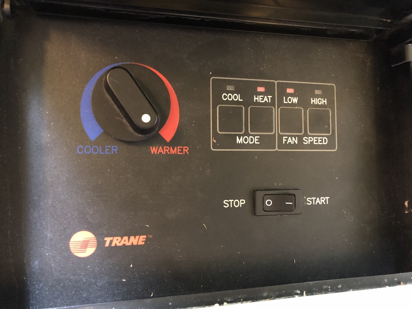
I was relaxing on my couch watching TV. Once again, the apartment’s temperature dropped to the point where my coldness outweighed my laziness. I got up and walked over to the heater to turn it on. Five minutes later, the apartment got too hot, so I walked over to turn the heater off. This was the process for controlling the temperature in my apartment. Until now.
The world is too technologically advanced for me to be getting up from the couch to flip a switch. Surely, there’s a product out there that would solve this problem for me. The closest thing I could find was the SwitchBot, a stand alone box that presses a button. To turn my heater on and off, I would need two SwitchBots, one for each side of the toggle switch. After reading the product reviews, I was unsure if the SwitchBot would even have enough force to press the toggle switch. Ultimately, I decided against spending $60 on an imperfect solution, and to make something bespoke to my heater.
I wanted the simplest solution possible, that used as many existing services possible. I learned from past projects that the more custom things are involved, the more there is to maintain.
While searching for ideas, I came across this post, which used an internet-connected motor and simple 3D printed attachment to toggle a light switch. This was it! I’d do the same thing, but with a different 3D printed attachment.
I wanted to get started right away. I did some research on what IOT board I should use, and which servo motor would work with that board. Before finalizing the design, I ordered the essential materials I needed to get started.
Materials:
- ESP8266 Wifi Development Board
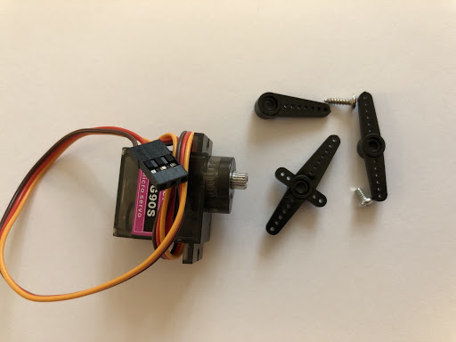
- MG90S Micro Servo Moto
- Jumper wires to connect the motor to the board
While waiting for the parts to arrive, I worked through the details of how I can tap a button on my iPhone or Apple Watch to make the heater turn on or off.
- I would have two buttons on my iPhone or Apple Watch, one to turn on the heater, and another to turn off the heater. The buttons would be Button Widgets on the free IFTTT app. There is no need to make a custom iOS app for two buttons.
- When a Button Widget would be tapped, it would make a web request to the ESP8266 board
- The ESP8266 board would be connected to my apartment’s wifi network, and listen for web requests
- Based on the request (on or off), the ESP8266 would execute a function to turn the motor to a specific position.
- The motor would be attached to the heater so that an attachment on the motor would flip the heater’s toggle switch.
With the details worked out, I could break down my solution into smaller tasks:
1. ESP8266 Board
a. Configure my Mac to upload code onto the board through the Arduino IDE.
2. Make the Motor Flip the Heater’s Switch
a.Figure out what can attach to the motor to flip the heater switch
Below, I will go into the details on each step so you can implement the same thing too.
1a. ESP8266 Board – Configure my Mac to upload code onto the board through the Arduino IDE
The Amazon page for the ESP8266 board has instructions to configure the board. The instructions are below, but I added an asterisk to the steps that required some modification:
- Download the Arduino IDE, the latest version.
- Install the IDE.
- Set up your Arduino IDE as: Go to File->Preferences and copy the URL below to get the ESP board manager extensions: http://arduino.esp8266.com/stable/package_esp8266com_index.jsonPlacing the “http://” before the URL and let the Arduino IDE use it…otherwise it gives you a protocol error.
- Go to Tools > Board > Board Manager> Type “esp8266” and download the Community esp8266 and install.
- Set up your chip: Tools -> Board -> NodeMCU 1.0 (ESP-12E Module)Tools -> Flash Size -> 4M (3M SPIFFS)Tools -> CPU Frequency -> 80 MhzTools -> Upload Speed -> 921600Tools–>Port–> (whatever it is)
- Download and run the 32 bit flasher exe at Github(Search for nodemcu/nodemcu-flasher/tree/master/ at Github) github.com/nodemcu/nodemcu-flasher/tree/master/Win32/Release Or download and run the 64 bit flasher exe at: github.com/nodemcu/nodemcu-flasher/tree/master/Win64/Release
- In Arduino IDE, look for the old fashioned Blink program. Load, compile and upload.
- Go to FILE> EXAMPLES> ESP8266> BLINK, it will start blinking.
4*. At the time of writing this, the latest version of the ESP core is 2.6.3. I was having issues with this version, so I had to install version 2.5.2.
5*.
- For Mac, you must install the NodeMCU v1.0 Driver for the the board to show up in Tools > Port. Follow the instructions here. I did have one hurdle while going through the Installer helper. You will have to allow the driver to have certain permission on the Mac. To enable those permissions on MacOS Catalina, you have to open System Preferences > Security & Privacy > General tab. At the bottom, enable the permissions.
- If the board is not showing up in the Arduino IDE > Tools > Port, make sure you are using the right USB cable. Some micro USB cables only supply power, and do not have the connections needed to transfer data. Ensure you have a micro USB cable that supports data transfer. This mistake cost me more time than I’d like to admit.
6*. Skip this step.
1b. ESP8266 Board – Write code that executes a function when a network request is received. Attach a servo motor to the board so it turns to a specific position when the function executes.
Below is the code that ultimately worked for me. I was experiencing some inconsistent behavior, so I added a lot of lines to try to fix the issue. As people in the linked forum have pointed out, the code could be simplified, but it works for me and I don’t want to risk having it stop working.
In the code below, replace “MyWifiName” and “MyWifiPassword” with your wifi credentials. Update gateway and subnet with the values of your network. On a Mac, you can find these values in System Preferences > Network > Advanced > TCP/IP. “Router” is the value for gateway, and “Subnet Mask” is the value for subnet.
// Import required libraries

#include <ESP8266WiFi.h>

#include <ESP8266WebServer.h>

#include <WiFiClient.h>

#include <Servo.h>

#include <ESP8266mDNS.h>

//Static IP address configuration

IPAddress staticIP(192, 168, 1, 176); //ESP static ip

IPAddress gateway(192, 168, 1, 1);   //IP Address of your WiFi Router (Gateway)

IPAddress subnet(255, 255, 255, 0);  //Subnet mask

IPAddress dns(8, 8, 8, 8);  //DNS


//On board LED Connected to GPIO2

#define LED 2

// WiFi parameters

const char* ssid = "MyWifiName";

const char* password = "MyWifiPassword";

////Declare a global object variable from the ESP8266WebServer class.

ESP8266WebServer server(80); //Server on port 80

Servo servo;

void handleLEDon() {

 Serial.println("LED on page");

 digitalWrite(LED,LOW); //LED is connected in reverse

 delay(20); // If the issue is caused by the watchdog timer, adding small delays fix the issue

 ESP.wdtFeed();

 servo.write(1);

 server.send(200, "text/html", "LED is ON"); //Send ADC value only to client ajax request

}

void handleLEDoff() {

 Serial.println("LED off page");

 digitalWrite(LED,HIGH); //LED off

 delay(20); // If the issue is caused by the watchdog timer, adding small delays fix the issue

 ESP.wdtFeed();

 servo.write(120);

 server.send(200, "text/html", "LED is OFF"); //Send ADC value only to client ajax request

}

void setup(void)

{

  pinMode(LED, OUTPUT);     // Initialize the LED_BUILTIN pin as an output

  // Start Serial

  Serial.begin(115200);

  WiFi.disconnect();  //Prevent connecting to wifi based on previous configurati
  ESP.eraseConfig();

  WiFi.config(staticIP, subnet, gateway);

  WiFi.mode(WIFI_STA); //WiFi mode station (connect to wifi router only

  WiFi.setSleepMode(WIFI_NONE_SLEEP);

  WiFi.begin(ssid, password);


  // Connect to WiFi

  WiFi.begin(ssid, password);

  while (WiFi.status() != WL_CONNECTED) { // blink to indicate the device is trying to connect to WIFI

    digitalWrite(LED,LOW);

delay(100);

    digitalWrite(LED,HIGH);

    delay(400);

    Serial.print(".");

  }

  Serial.println("");

  Serial.println("WiFi connected");

  if (MDNS.begin("esp8266")) {

    Serial.println("MDNS responder started");

  }

  // Start the server

  server.on("/ledOn", handleLEDon); //as Per  <a href="ledOn">, Subroutine to be called

  server.on("/ledOff", handleLEDoff);

  server.begin();                  //Start server

  Serial.println("HTTP server started");


  // Print the IP address

  Serial.println(WiFi.localIP());

  digitalWrite(LED,LOW);

 ervo.attach(14); //GPIO15 = D5

  servo.write(1);

}

void loop() {

  server.handleClient();          //Handle client requests

  MDNS.update();

}
These were my settings on the Arduino IDE when I uploaded the code to the board:
– Tools > Board > Board Manager > esp8266 by ESP8266 Community version 2.5.2 installed
– Tools > Board > NodeMCU 1.0 (ESP-12E Module)
– Tools > Upload Speed > 115200
– Tools > CPU Frequency > 80 MHz
– Tools > Flash Size > 4MB (2M SPIFFS)
– Tools > Debug port > Serial
– Tools > Debug Level > None
– Tools > IwIP Variant > v2 Lower Memory
– Tools > VTables > Flash
– Tools > Exceptions > Disabled
– Tools > Erase Flash > All Flash Contents
– Tools > SSL Support > All SSL ciphers (most compatible)
– Tools > Port > /dev/cu.SLLAB_USBtoUART
Attach the servo to the board:
- Ground on the servo (the brown wire) to the GND pin on the board
- Power on the servo (the orange wire) to the 3V3 pin on the board
- Data on the servo (the yellow wire) to the D5 pin on the board
When the board is powered, the built in LED will blink as it attempts to connect to the wifi. Once it connects, you can use a web browser (such as Chrome) on your computer that is connected to the same wifi that the board is on, and enter http://192.168.1.176/ledOff or http://192.168.1.176/ledOn and the servo will turn to the corresponding spot.
1c. ESP8266 Board – Make the board consistently visible to the outside internet, so IFTTT can make the request to the board
With the previous step complete, you can control the motor from your browser, but only when you are connected to the same wifi network. Since we will be using IFTTT to make the network requests, we need to make the board accessible to the world wide web.
After completing my project, I learned that the ESP8266 has a mDNS library that I include in the code, but do not use. There might be a way to avoid this step if you use the mDNS library correctly. However, I did not, so I created a Dynamic DNS for my home wifi, and setup port forwarding to my ESP8266 board.
To create the Dynamic DNS, I followed the instructions here, using No-IP as the provider. My router’s admin portal (login info will likely be on your router) has a DDNS configuration option that works with No-IP, so my router should automatically update my internet’s IP address with the domain name I created.
To setup port forwarding, in your router’s admin portal find the Port Forward option. Setup a rule where the “Internal Host” is 192.168.1.176, and the “Internal Port” is 80. Both of these values were set in the code. For “External Host”, I put an asterisk, which is a wildcard value. For “External Port”, put in a value of your choosing, for example 8880. To validate that this work, power on the board that is running the code above. Then go to https://www.portchecktool.com/, and enter the external port. You should see a successful connection.
Now, you can validate that everything worked. On a browser that isn’t on the same wifi network as your board (I used my cell phone with wifi turned off), enter yourDynamicDDN:8880/ledOn or yourDynamicDDN:8880/ledOff (for example, http://myHeaterServo.hopto.org:8880/ledOn). This will execute the corresponding functions of the board.
1d. ESP8266 Board – Setup the IFTTT recipes
Now that the board is accessible from anywhere, set up IFTTT to execute those two network requests from the above paragraph. Create two recipes where the “THIS” is the Button Widget, and the “THAT” is a Webhook – Make a web request. The URL is the request from the above paragraph. Method is GET. Content Type is application/json. And Body is blank.
Now you can download the IFTTT app for your iPhone, and add the IFTTT widget to your iPhone’s Today View for easy access to the two buttons. You can also download the associated Apple Watch IFTTT app, so you can tap those buttons from your watch!
2a. Make the Motor Flip the Heater’s Switch – Figure out what can attach to the motor to flip the heater switch
This was a quick step for me. The servo motor came with a few attachments for the motor, and the one pronged attachment was enough for me.
2b. Make the Motor Flip the Heater’s Switch – Make an attachment for the motor so it’s positioned precisely over the heater’s toggle switch
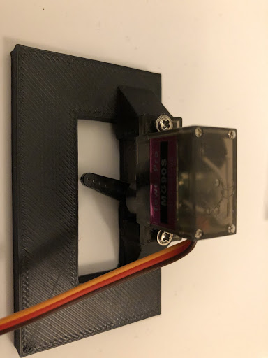
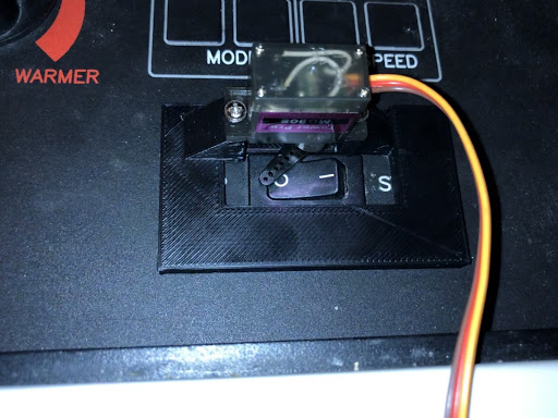
I measured the heater’s switch, and created a 3D model of the attachment that the motor could be screwed to. I used this 3D model of the motor and created an assembly of all the pieces so I could precisely position the motor over the switch.
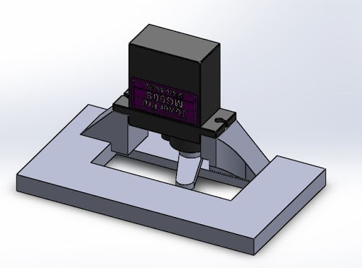
Attachment with motor screwed in. This assembly verified the motor would be positioned correctly over the toggle.
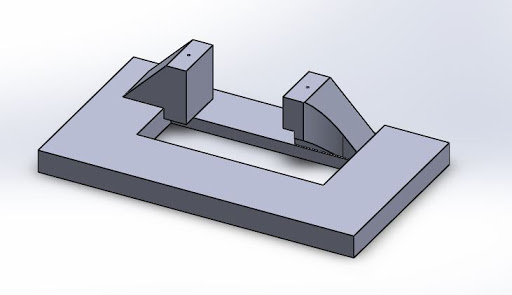
Attachment without motor. This is the part to be 3D printed
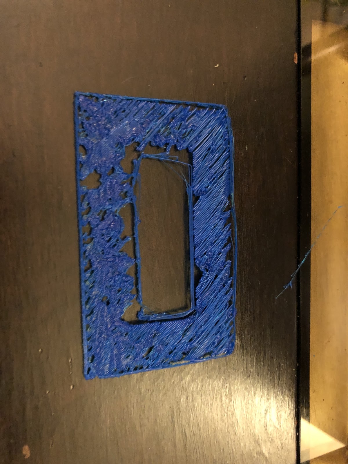
I tried for a while to get the 3D print the part myself. Two years ago, my friend found a 3D printer on the curb, and offered it to me. For the past two years, my wife has been telling me to throw it out, since it was taking up valuable space in our small NYC apartment. But I insisted I would use it, and here was the perfect opportunity! Unfortunately, after two frustrating nights of trying to 3D print the piece, it didn’t work. Now I am considering putting that 3D printer on the curb myself (but don’t tell my wife).
I gave up and spent $13 for MakeXYZ to print it for me. Their shipping speed and cost was better than Hub. I set the infill density to 85%, so I could screw into the piece when attaching the servo. These were my settings: Process: FDM. Material: Plastic. Color: Black. Infill: 85%. Layer height: 0.2mm
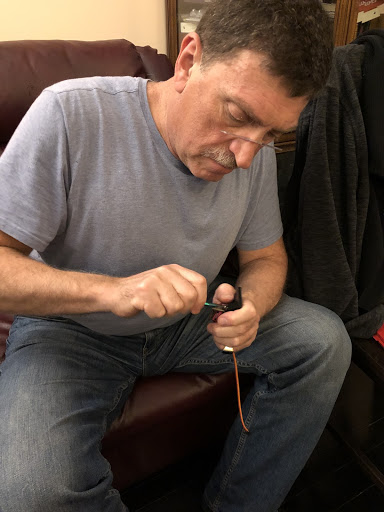
After a week of waiting, the piece finally came! My parents were over at the time, so my dad helped me drill little holes into the piece and screwed the motor to the piece. He likes doing this kind of stuff too.
However, there was a small issue with the print. I used the wrong length measurement of the heater’s switch when modeling the piece, so it would be able to slide along the switch.
I didn’t want to wait another week to remodel and reprint the piece with the correct dimensions, so my wife and I searched our apartment on what could fill the empty space. Eventually, we found some matches that would fit perfectly in the openings if three matches were stuck together.
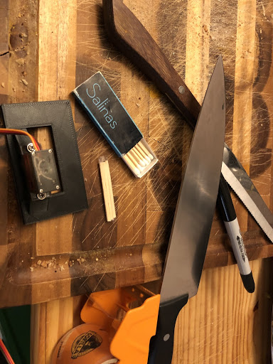
I taped 3 matches together, measured (twice) where to cut them, and chopped them with a kitchen knife. It worked flawlessly.
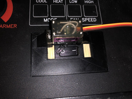
I taped the piece onto the heater with shipping tape. To prevent any sort of sparks, I covered the board’s pins with electrical tape, in case it touches a metal part of the heater. And finally, I plugged in the board to a long micro USB cable, and taped the wire so it’s a little out of the way. I propped open the cover of the heater halfway to prevent any overheating of the board.


That is it! Now I can control the temperature of my apartment from my watch, without having to get up again. Sometimes, it takes a lot of effort to be lazy.
In the future, I’d like to add an IOT temperature sensor to automatically turn on/off the heater if the temperature drops below a certain value.